I got a two-armed robot, an OpenArm, to lay a brick wall. It laid a wall of five bricks in real mortar, three on two, under a recursive state machine. That was six weeks after the arm went on the table.
This post goes through how I got there, in order: why bricks at all, the bricklaying course I did first, the first day of teleoperation (teleop), the gripper I designed and printed, the topology optimiser I wrote for it, the mortar tool for the left arm, and then the wall.
I didn't train a vision-language-action model to do this. A wall is a known shape, so we know where every brick has to go. I used depth sensing, a physics model of the robot and reinforcement learning (RL) instead.
The short list of what I learnt:
- I learnt to lay bricks first. I did a bricklaying course and built real walls, so the robot's success criteria (gauge, level, plumb and line) came from the trade. (Learning the Trade)
- Both arms followed me on day one, within an hour and a half of first power-on. It felt right, but one wrist had answered 12 of 198,882 commands and the bus raised no error. I trust reply counts over feel now. (Day One)
- I designed and printed my own gripper. It went through five revisions, with every part built as code and checked by scripts. The G3, our final right-hand gripper, is the one that laid the wall. A model is only as good as its fixed side, the thing it bolts to. One bracket passed 284 fit checks and then hit a ring on the arm that the model never had. (The Fixed Side)
- I wrote a topology optimiser to cut windows into the housing. It's 179 lines of numpy and scipy, and it took 29.5 g out of the gripper through twelve windows, with the build's stress and fit checks still passing. (Topology Optimisation)
- For the mortar tool I ran 768 agents in one evening and night. With two smaller rounds earlier that day, that's 118 distinct designs across 119 CAD builds. I had 103 of them checked against the mortar's rheology, meaning its yield stress and what a heap, a vertical joint and a laid brick can take. Each was also checked on loaded mass and the motor's travel, and the 103 went through 2,729 challenges. From them I built one bowl and one vane on one motor. (Mortar on Paper, One Bowl)
- I slide the bench between the two arms by hand, and a recursive state machine runs the lay. In simulation the arms share no spot in front of them where both can work, so the bench takes the wall to each arm in turn. (First Wall)
Why Bricks
Before I designed anything, I wanted to know why robots aren't laying bricks on site already. I started from Brian Potter's essay "Where are the robotic bricklayers?",1 then went through the companies in the field and what masons say on forums.
In short, nobody's made robot bricklaying cheaper than a mason yet. The systems that survive either keep a skilled person beside the machine, or change the brick to suit the machine.
The headline rates shrink on site. FBR's Hadrian X had an early target of 1,000 blocks an hour, and the threshold in FBR's own 2024 US agreement was at least 285 an hour.2 Across the field, headline speed is 2 to 5 times site speed.
I trust the forums more than the marketing, and masons there count everyone the machine needs before they get to laying speed. The top comment in one r/masonry thread reads: "It can do the job of 3 men. All it takes is 3 men to feed the machine."3
Charlie Collison, a UK bricklayer, filmed himself laying 3,360 bricks in a day in 2021, with three labourers feeding him bricks and mortar and finishing the joints behind him.4 Across four people that's 840 bricks each.
SAM, a US bricklaying robot, was marketed at 2,000 to 3,000 bricks a day. With its crew of three, that's 667 to 1,000 each. A single UK bricklayer lays about 500 a day.
Switch the count to per person to see the gap close.
- First-timer, 8 h20
- Practised DIYer, 8 h160-200
- Pro, 8 h480
- UK gang, 2 + 11,200-2,000
- Collison's day3,360
- Findlay's day2,500
- SAM100 headline2,000-3,000
- Our wall5 in an afternoon
The gold tick on our row is what our crew must lay to match Collison's 840 a head. A target, not a measurement: the first wall was five bricks in an afternoon.
- Best per crew
- Collison's day, 3,360 a day
- SAM per head
- 667-1,000 [C]
- We must lay
- 840 a day with 1 person to match Collison a head
Human rates from bricklaying forums, videos and trade sources (the first-timer's "4 hours to lay 10 bricks" scaled to 8 h, a pro at about 60/h × 8 h). Collison 3,360 in 7 h 40 min, himself and three labourers, from his filmed day. Findlay about 2,500 with six. SAM 2,000-3,000/day headline, "needs 2-4 workers". Blocks (Hadrian, MULE) are left out: other units. Our wall has no day rate yet: the first one was five bricks in an afternoon.
So a robot wall has to be judged the way a mason's wall is, on real bricks and real mortar, with every person counted. The day after the arm arrived, I wrote down the wall I set out to build:
- 3 courses in running bond, also called stretcher bond, where each course sits half a brick along from the one below.
- About 2.5 bricks long, with half bricks at the ends.
- Bonded with real mortar, and level to ±2 mm.
My brick is a UK standard 215 × 102.5 × 65 mm cored brick. These weigh 2.0 to 2.5 kg, so I took 2.5 kg as the design load. The ones I ordered that week were listed at 1.95 kg.
Learning the Trade
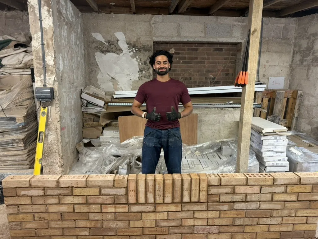
I did a bricklaying course at a college before the arm arrived. I built real walls there, so I know how a brick wall is laid and how it's judged. The course covered half-brick and one-brick walls, 90° corners, attached piers, neat cuts and pointing.
I started with a straight wall.
The next day I built a pier, a square column of brick that stands on its own.
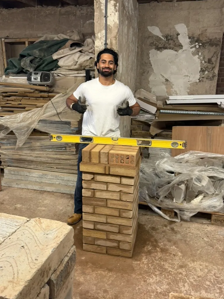
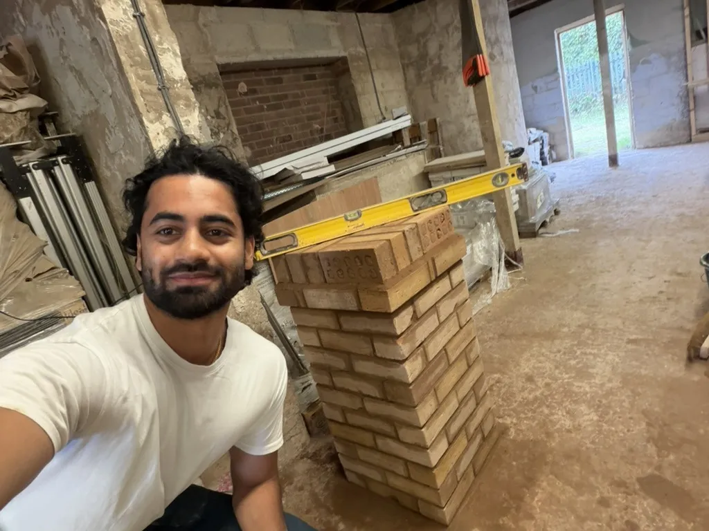
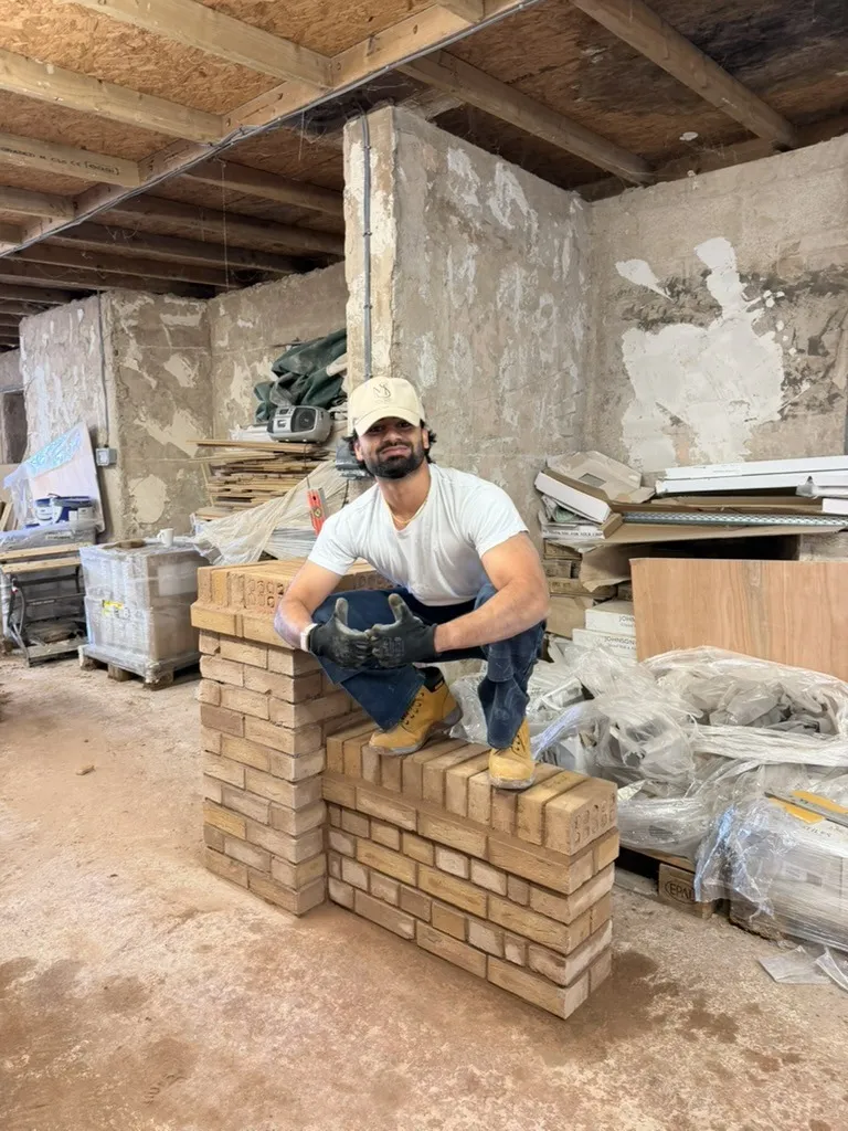
After that I built a pier with a wall coming off it at 90°, which is called a return.
The wall I'm most pleased with is the one from the last day of the course, the tallest of the four. It has a window opening with a lintel across the top, and a row of soldiers, bricks stood upright, along the bottom as the sill. There's a dentil course as decoration, where every other brick projects from the face, and blockwork behind the brick, with a damp-proof membrane and wall ties between the two leaves. It really tied together everything I'd learnt.
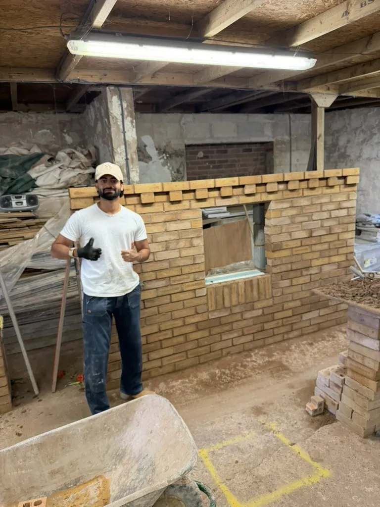
Every one of those walls was judged on the same four checks:
- Gauge. A brick is 65 mm high and the mortar joint under it is 10 mm, so every course adds 75 mm and four courses make 300 mm. You hold a gauge rod marked in courses against the corner to check it.
- Level. The top of each course is flat, checked with a spirit level laid along it.
- Plumb. The face and the ends are vertical, checked with the same level held upright.
- Line. Between the corners you stretch a string tight, level with the top of the course, and lay every brick to it. You keep a trowel's thickness off it, because a brick that touches the line pushes it out and the wall comes out curved.
These four became the robot's success criteria. The top of course n has to sit at 75n mm, level to ±2 mm, on the line, and plumb on the face and both ends.
From the line I also took a rule I used later for the gripper. A brick that sits high gets tapped down to the line, and the mortar bed under it gives. A brick that sits low has to come off and be re-bedded, because you can't pull a brick up. So masons control height, not force, and my gripper does the same (Gripper as Code has the mortar numbers).
Day One
Here's the robot on my table.
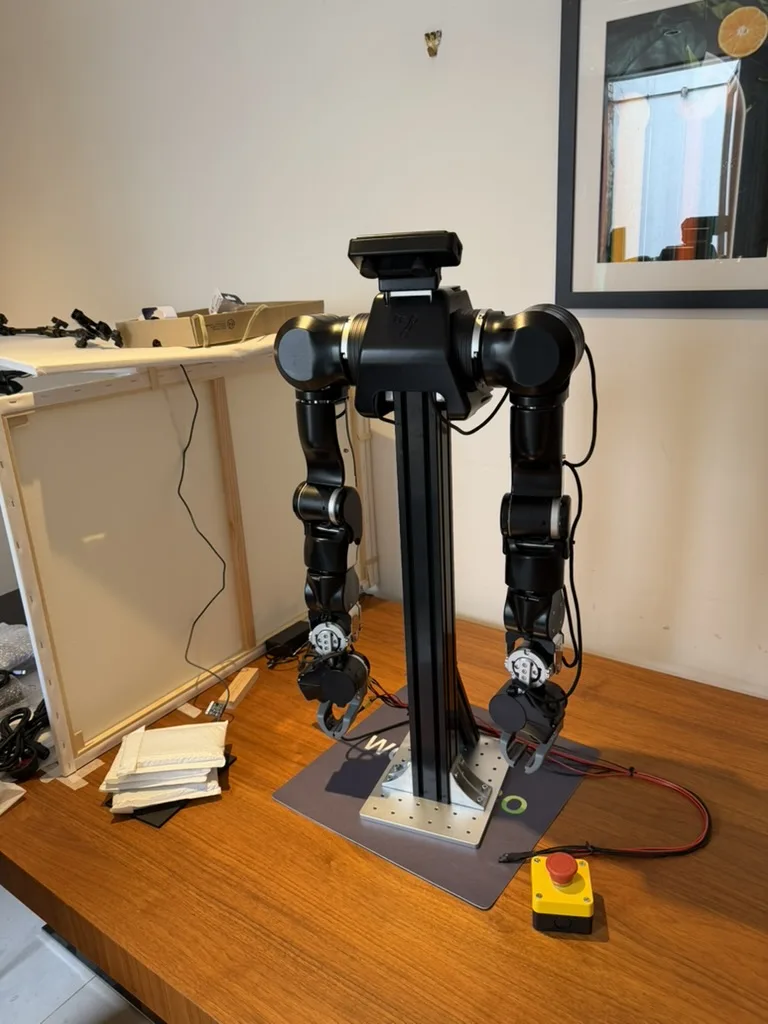
It's an OpenArm 2 from Enactic. It has two arms with seven joints each, J1 at the shoulder to J7 at the wrist, and an eighth motor, J8, that drives each gripper. Each arm weighs 5.5 kg and reaches 606 mm.
Both arms get their power through that yellow emergency stop (e-stop), and they have no brakes, so pressing it drops them. With the e-stop pressed, a scan for motors also comes back empty on both arms and counts no errors. If you ever see that, check the e-stop before you touch a connector.
Both arms still had their stock grippers.
To drive the arms I used the KER, the leader arm in the photo below. You wear it like a backpack and move your own arms, and the robot's two arms follow. That's what teleop means here.
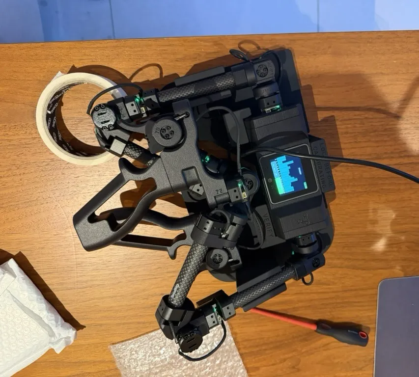
It's a 1.7 kg replica of the arm at 70 % of the link length. It has 16 magnetic encoders and no motors, so it reads my arms but can't push back.5 We later stopped using it, because it was difficult to use and it didn't follow the elbows properly.
The motors talk over CAN-FD, one bus per arm, through SocketCAN. SocketCAN is Linux only,6 so the robot's PC is a fresh Ubuntu Linux install. The only official software route for the KER was Enactic's nodes for dora, a dataflow framework.7 I ran three of them on a 250 Hz tick, one that reads the KER and one that drives each arm.
Both arms were following me within an hour and a half of first power-on, and it felt right. But the left J6, a wrist joint, had answered 12 of 198,882 commands. The bus raised no error, because CAN acknowledges a frame if any node on the bus hears it. So I count replies now and don't trust feel.
Tool Vertical
The first design question was how the wrist should hold a brick. The numbers come from the arm's URDF, its robot description file, and a 2.5 kg brick.
With the tool horizontal and the brick's centre 0.17 m out from the wrist, the torque on J6 is 2.5 × 9.81 × 0.17 = 4.17 Nm. The wrist motor is rated at about 3 Nm by its maker and peaks at 7 Nm. So that wouldn't drop the brick, but held for minutes it might overheat J6.
The arm's geometry makes that torque go away. The J5, J6 and J7 axes all pass through one point, the wrist centre. So with the tool pointing straight down and the brick hanging under that point, all three wrist motors carry zero gravity torque.
That weight still lands on the shoulder, so the arm has to work close to the body. An Enactic engineer measured only 1.6 kg at full reach on an earlier arm, not counting the end effector, against a listed rating of 4.1 kg with it.8
The grip comes from the wall. A mason's brick tongs grip the ends of the brick, but in a wall the neighbouring bricks touch the ends, so jaws have nowhere to go there. The long stretcher faces are the wall's own faces, and they're free.
The view from above shows that grip, with the pads on the long faces.
- Width grip
- pads touch only the two faces of the wall
- Needs
- about 125 mm of parallel stroke
- Stock gripper
- about 110 mm (derived), angled fingers
My planning notes: the neighbours touch the ends (0 mm dry, 10 mm with mortar). The stock gripper opens about 110 mm between fingertip centres, derived from the OpenArm URDF, not measured. A width grip wants about 125 mm of stroke. Plan view to scale, pads schematic.
The stock gripper can't do that grip. Its fingers pivot, so its jaws are never parallel, and it opens about 110 mm, a number derived from the URDF and never measured. A grip across the width wants about 125 mm and flat pads. So I designed my own gripper and called it G2, a parallel-jaw clamp driven by the J8 motor.
Gripper as Code
G2 went through five revisions, A to E, and every part of every revision is a script. The last model in the figure is the G3, our final right-hand gripper, the one that laid the wall.
Step through the revisions in the figure and turn each model as you go.
8 of 8
The G3
The same motor, pinion and racks, with everything kept below the sweep of the wrist. J7 turns ±90° where rev E stopped near ±40°, the hand is 140 mm wide against 218 mm, and in simulation it reaches about twice as many places on the wall.
- Status
- On the arm, placed every brick of the wall
- Mass
- about 0.7 kg (estimate)
The CAD model of each revision. Masses and print status: my build log. The G3's range, width and reach: its design study, where the reach is a simulation. Masses marked estimate are CAD estimates.
The scripts run in ClassCAD, a CAD engine you drive with code. The engine can report success for an operation that did nothing, so every part script checks its own volume against arithmetic.
My own checks could still pass a broken part. The clash checker measured the overlap of two parts with a Boolean operation, and when the operation failed it recorded the overlap as −1. The rule asked whether the overlap was under its limit, and −1 is under any limit, so a build that reported 288 passes could still hide a clash. A check that can't measure has to fail.
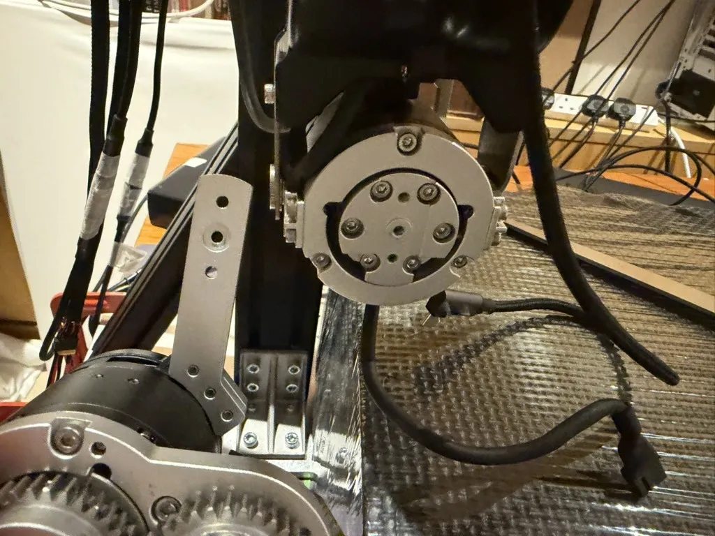
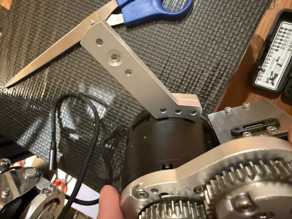
Rev A's mount was a placeholder, a flange I'd assumed the arm had. There's no flange on the end of the arm. The tool bolts straight onto the output disc of the J7 motor, with 6 × M3 screws on a 27 mm pitch circle.9 When I took the stock gripper off, I found an aluminium block bolted straight to the disc.
Rev A also held the brick on four springs. A switch tripped at 7 mm of travel, so the brick went onto its bed at 64.6 N every time. That constant bed force was wrong. Mortar stiffens as it stands, so the force a bed needs changes. By our arithmetic, not yet tested on a real bed, fresh mortar squeezes to a 10 mm bed at 2 to 23 N, and the test brick alone weighs about 19 N. Stiff mortar needs 90 N or more.10
A fixed trip force would give a different bed thickness every time. So the gripper controls height, not force, as in Learning the Trade, and reads first contact from the torque step on J2 and J4.
Revs A to C stayed on paper, and the estimated mass grew from 849 g to about 1,380 g against a budget of 1,000 g for the whole tool. The first printed gripper was rev D. I print in PETG, and rev D is all printed apart from its springs and one Ø5 stainless tube that I cut into hinge pins. The big parts take about 30 hours at 100 % infill.
I test each fit on a coupon first, a small test piece you print, try the real part in and throw away. We'd guessed that PETG prints holes 0.1 to 0.2 mm small. When the tube arrived, it turned freely only in the largest vertical hole of the coupon, Ø5.3. In the sideways coupon, Ø5.3 was snug and the smaller three wouldn't take it. The four links I'd already printed, with Ø5.2 eyes printed sideways and 15 mm long, wouldn't either, so I reprinted them.
The guess was about half of what the fit test showed, and the error depended on direction. So one tube got three drawn bores:
- The bracket cheeks print vertical, so Ø5.3.
- The carrier cheeks print sideways but are only 3 mm thick, so Ø5.4.
- The link eyes print sideways and 15 mm long, so Ø5.5.
Pick a preset in the figure to see why the Ø5.2 eye fails.
- Printed
- Ø4.85
- Clearance
- −0.15 mm
- Verdict
- will not enter
Offsets from my printed test coupons, n = 1 each, not gauged: vertical Ø5 hole −0.25, sideways 3 mm cheek −0.30, sideways 15 mm eye −0.35 (a drawn 5.5 prints at about 5.1 to 5.2), vertical Ø17 ring −0.12 on the Ø16.96 spigot, horizontal boss +0.2 against the Ø6.47 counterbore (root coupon). Tube Ø5.00.
My theory is the seam, the small blob the printer leaves at the same point on every layer, plus the hot bead pulling inward on a tight arc and the roof of a sideways hole sagging. I didn't measure any of these causes.
The Fixed Side
Two printed rev D parts passed every check and then didn't fit the real motor or the real arm. One was the carrier, the frame that holds the J8 motor. The other was the bracket, the part that hangs the gripper off J7.
My model of the J8 motor, a Damiao DM4310, came from a reference CAD file named DM4310_simplified. The real one stopped part-way into the carrier and snapped a post off, so I got the calipers out.
The diameter read 57.43 and 57.18 mm against 57.0 drawn. The Ø57.4 hole had printed at about 57.1. From the output disc to the back of the cap, the depth was 54.04 mm against 51.5. The model had the plug on the back face at 75°, and the real socket sits in the side at 105°.
The drawn motor is next to the measured one below.
- Ø
- 57.43 / 57.18 vs 57.0
- D1
- 54.04 vs 51.5
- Tab in slot
- 7.07 in 7.36 printed
- XT30
- 105°, in the side
The Ø57.4 cut printed at about 57.1. The cap stands 7.97 behind the body, not 5.5. Depth readings 52.72, 52.86 and 54.12; 59.32 to the output disc; 67.89 to the top.
Drawn: the rev D.3 CAD model. Measured: my caliper readings of the J8 motor, three readings each, with the printed slot from rev D.5.
The bracket was the bigger problem. The J7 joint has an outer silver ring, J7_A, and it was never in my model. Two trunnion posts bolt to it and run in the bearings of the J6 fork, so it's what holds the J7 motor in the forearm and it can't come off.
In the full OpenArm 2.0 CAD file the ring is 8.5 mm of fixed metal along the J7 axis, from x −1.0 to +7.5. The bracket's cradle ran from x 0.5 to 9.5, straight through the ring's lower crescent, with 2,322 mm³ of overlap.11
Drag the slider to move the cut along the axis and watch the cradle cross the ring.

- Bracket
- D.4 at x 6.0
- Ring
- present (x −1.0 to 7.5)
- Overlap here
- 332.5 mm²
- D.4 through the ring
- ≈ 2,328 mm³
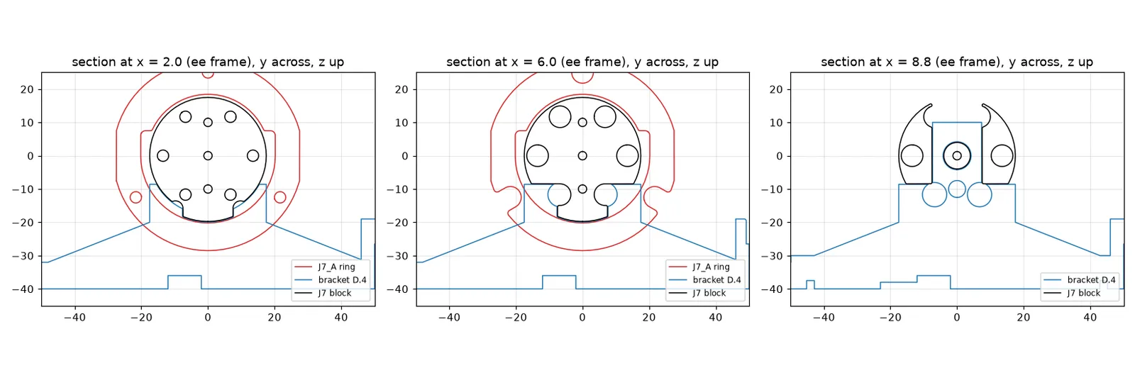
The J7_A ring mesh is one of 135 parts in the J7 group of the official OpenArm 2.0 STEP model. The rev D.4 bracket, rev D.7 bracket and J7 block come from my CAD models. The planes are cut from those meshes. The volume is a 0.5 mm grid estimate, and the 2,322 mm³ is an exact Boolean intersection of the meshes.
That bracket, version D.4, had passed the clash check, a sweep of the wrist about J6 against the forearm, and 284 fit checks with no failures. All of them ran against the arm in the model. Three causes matter most:
- The only arm-side geometry was a CAD file of the end effector plus the J7 motor.
- I treated a part named
DM4310_simplifiedas exact, the same cause as the carrier. - The ring is plainly visible in my photo of the joint, and I hadn't looked for it.
So a model is only as good as its fixed side. My checks on the moving side, the jaws, racks and links, were thorough, but the arm itself was a cylinder and a boss from someone else's file. Three things changed:
- Fixed-side geometry comes from the full arm CAD file.
- A new check,
arm_clash.py, runs the whole gripper against it on every build. - Every simplified or stock dimension a printed part touches gets measured on the real arm before the part prints.
On its first run the arm clash check confirmed the 2,322 mm³. It also found a 0.08 mm near miss between the cradle and a trunnion post at J7 ±30°, the software limit I'd set to keep the J6 fork off the bracket. A carrier is a 10 h 29 min print and a bracket 6 h 46 min, so the check has to find these first. D.6, the replacement bracket, moved its root behind the ring.
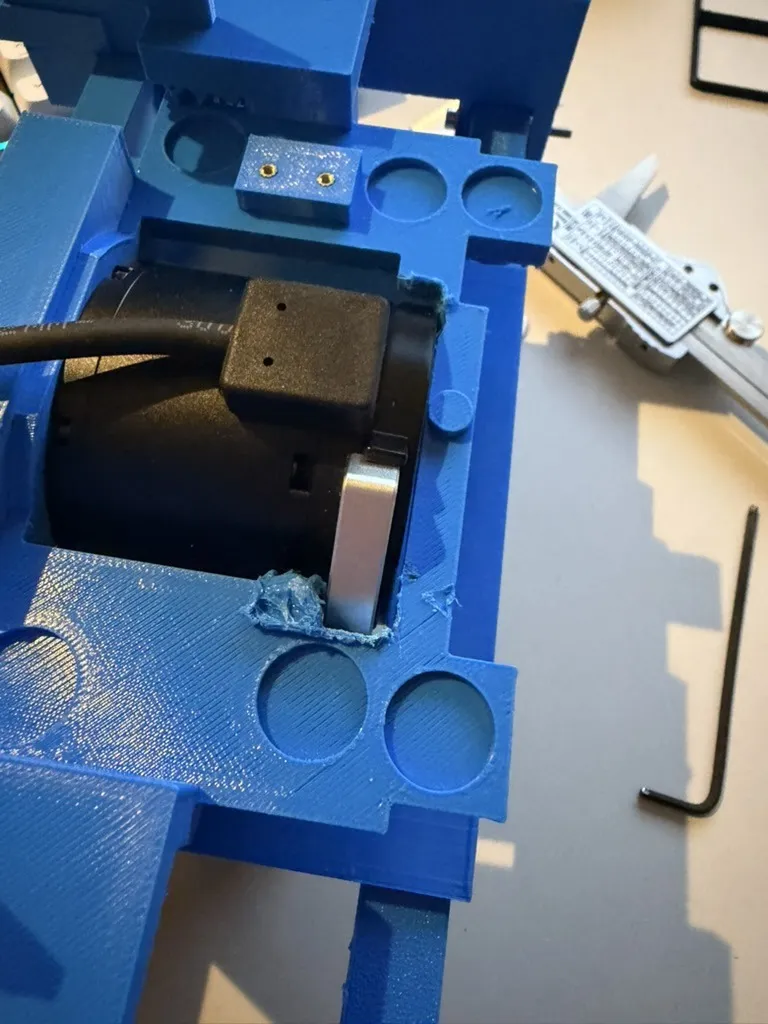
For D.5, the next carrier, I wrote an insertion sweep that lifts the motor 70 mm into the carrier in 1 mm steps and measures the overlap at each one. It passed, and the printed D.5 still didn't take the motor. The motor in the sweep was still the simplified file. The real one has a small silver tab on its rear with two black plastic holders beside it, 29.3 mm wide where the file had 25.
I fixed that one on the bench, melting the tab gap and the back corner with a soldering iron until the motor went in (hot PETG gives off fumes, so ventilate). That carrier is the one that went on the arm.
My plate-building script became shambu, a public tool that builds Bambu Studio print plates from the command line.
Then the gripper went on the arm and cycled open and closed 31 times in 118.7 s, with each end repeating within 0.0007 rad. There was no stall, motor error or missed reply.
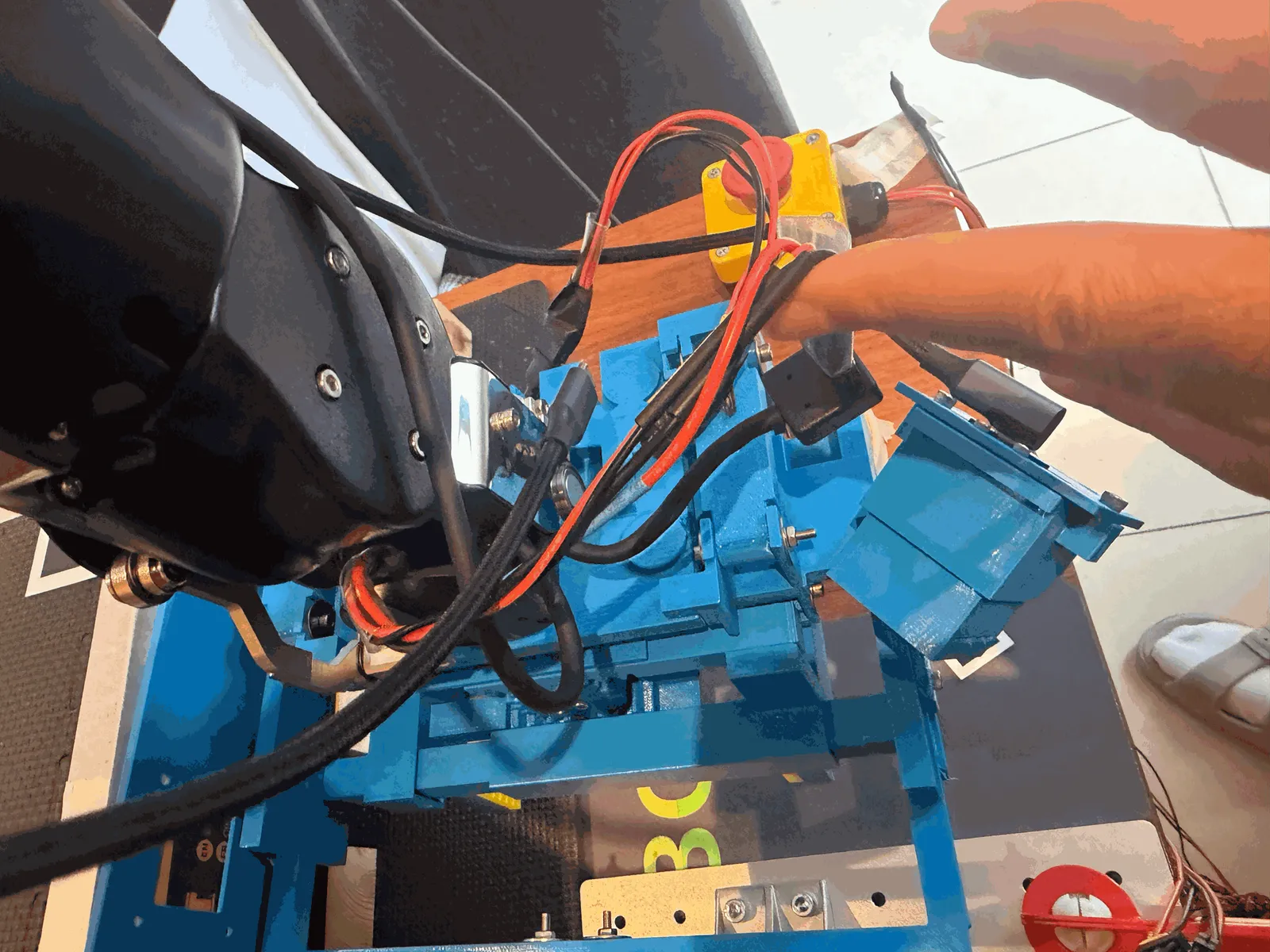
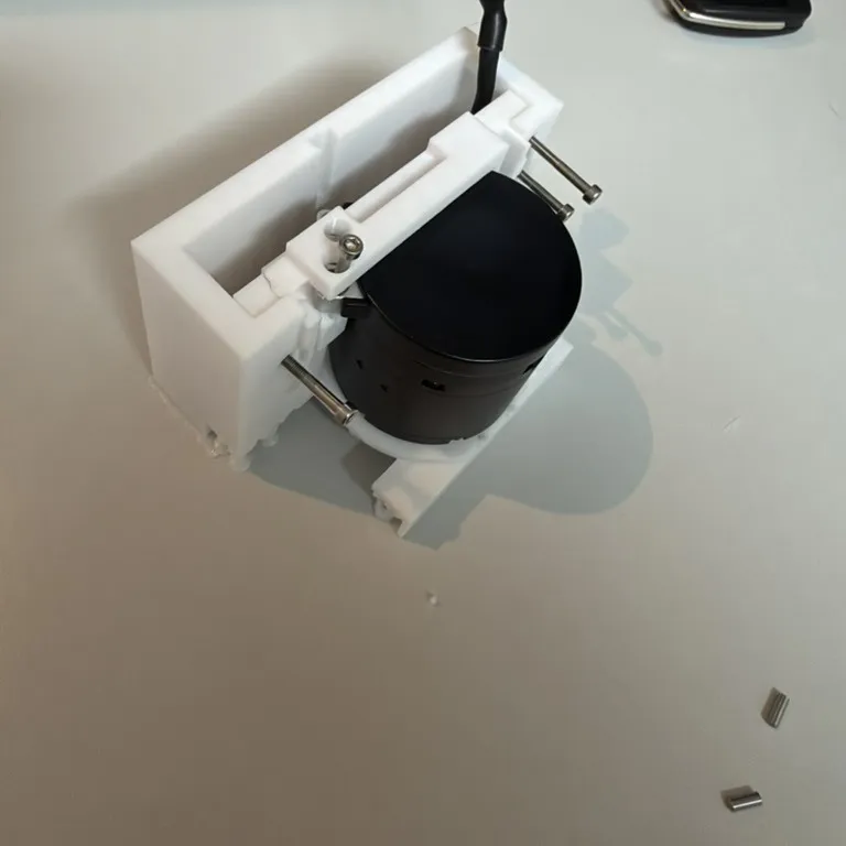
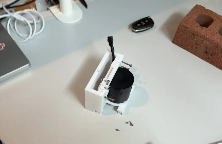
The model also had the J7 motor as a plain Ø57 mm cylinder. The real one has its power and CAN plug on the side, so the lead bends hard onto the printed ceiling, circled in the left photo. The right photo is the looms, which the model didn't route either. The simplicity we'd assumed for speed came back to bite us later.
 leads on the ceiling
- Model
- J7 = plain Ø57 cylinder, no lead
- Finding 1
- leads bend hard on the ceiling
- Finding 2
- no routing for either loom
- CAD change
- none: "logged here only"
My phone photos of v1 on the right arm, and the findings from my print log for G2 v1 as built. The right photo is cropped, and the ring is drawn by eye.
The next bracket, D.7, got a 10 × 70 mm notch through its ceiling for the plug, sized from a ±30° sweep of the plug. The printed D.6 overlaps the plug by up to 1,138 mm³, and D.7 stays 1.4 mm clear. That sweep is the first of the five looping clips below.
The wrist plug against the bracket
The plug of the wrist motor swings with J7. It cuts through the bracket I printed first (left) and passes through the notch of the next one (right).
- D.6
- up to 1,138 mm³ inside the bracket
- D.7
- 1.4 mm clear at every angle
Arm clash sweep, rev D.7
The gripper turns J6 50° each way at J7 0°, +30° and −30°, against the forearm and the wrist linkage.
- Closest
- 2.6 mm at J6 −50°
- Needs
- 1 mm · PASS
J6 sweep, rev E.7
Every part of the rev E gripper turns J6 60° each way at J7 0°, ±30° and ±40°. The check counts J6 ±50° at J7 0° and ±30°.
- Closest
- 2.6 mm at J6 −50°
- Needs
- 1 mm · PASS
- Past the check
- 0.03 mm at J6 −60°, J7 +40°
Motor into the carrier, rev D.7
The J8 motor rises 70 mm into the carrier in 1 mm steps, the way it goes in by hand.
- Overlap
- 0 mm³ at all 71 steps
- Limit
- 0.5 mm³ · PASS
Cradle into the housing, rev E.7
The motor cradle slides 60 mm sideways to its seat in the rev E housing.
- Overlap
- 0 mm³ at all 61 steps
- Limit
- 0.5 mm³ · PASS
Rendered from the gripper CAD of revs D.6, D.7 and E.7 against the arm model, with the clearance or overlap computed again for each frame. The plug overlap and gap were measured at J7 −30°, 0° and +30° only. The arm parts are derived from Enactic OpenArm CAD, CERN-OHL-S-2.0.
By then the full set of checks took 61 minutes. Half of it was one loop that tested 2 to 3 million gripper points against every arm part at each of 606 sweep steps. Skipping only the points that provably can't reach the arm took it to 2 min 59 s, with identical answers.
Rev E is G2 rebuilt as one rigid housing. The sprung lift could never finish, because the J8 plug meets the ceiling at about 8 mm and the hard stops sat at 10 mm. So the lift and the springs went. The new housing bolts to the J7 block and carries the J8 motor, the drivetrain and the camera. The laying swing only works with the gripper facing the other way, so I also turned it 180°.
My rule was never to loosen a check to make it pass. So every failed check meant more plastic, and the motor cradle grew from 8,908.8 mm³ to 15,040.0 mm³.
Watch the third clip, the rev E housing redrawn at each of its 52 CAD snapshots, beside the bracket and carrier it replaced.
Bracket, revs B to D
The part that bolts the gripper to the wrist, redrawn across three revisions.
- Snapshots
- 55
Carrier, revs B to D
The part that carries the J8 motor, redrawn across the same three revisions.
- Snapshots
- 39
Housing, rev E
The rev E housing from its first build to E.8b, where the windows open in the walls.
- Snapshots
- 52
One frame per saved CAD snapshot of the part, in the order the snapshots were taken, at the same camera.
The joint between the motor plate and the lid seemed weak and a likely breakage point. The internal corners there were sharp, and a hand calculation put the junction at 37.17 MPa against a 35 MPa limit. E.7a added 3 mm fillets and gussets for 3.4 g, and that fell to 1.97 MPa.
I printed a coupon of the motor bay before the 18 hour print of the housing and its small parts, and the motor went straight in.
Topology Optimisation
We wanted the gripper lighter and better looking, so I wrote a topology optimiser to decide where to cut windows in the rev E housing, about 265 g of PETG at build E.7a. A mesh from an outside tool would have skipped my fit, stress and clash checks.
About 48 cm³ of the shape above the motor, 16 % of the housing, was only there because its outline was the old carrier's footprint. My checks asked whether each wall was strong enough, never whether it was needed.
The optimiser is SIMP in 179 lines of numpy and scipy, in the style of top3d,12 and it runs on the housing's own mesh with the loads my stress checks use. SIMP gives every cell a density between 0 and 1 and makes stiffness go as the density cubed. A half-dense cell costs half the plastic for an eighth of the stiffness, so the optimiser pushes every cell to solid or empty.13 It only removes material, so nothing it suggests can hit anything new.
The housing is clamped where it bolts to J7 and loaded four ways: a 57 N brick catch, 3 Nm of J8 torque, 1.5 times gravity sideways and 61 N spreading the rack lips. Switch between them here.
- Load
- 57 N along −z
- Where
- four rail sockets, 14.25 N each
- Basis
- 3 g on the 1.95 kg brick
- Note
- 2.5 kg design brick → 73.6 N
The supports and the four load cases as the topology solver applies them, on the 2 mm voxel grid of the E.7a housing. Arrow positions are the real coordinates; arrow lengths are schematic.
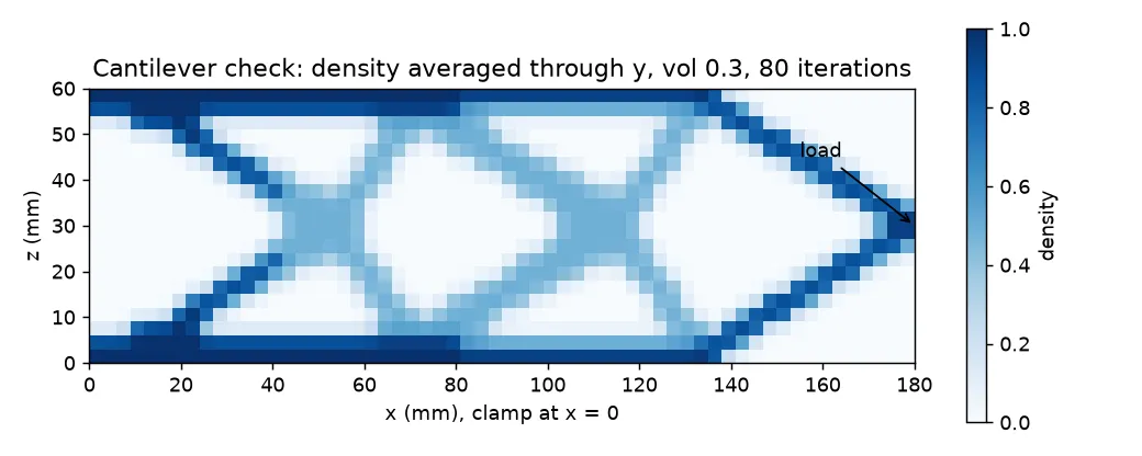
First I tested it on a 180 × 12 × 60 mm box, clamped at one end with 100 N on the other. The right answer is Michell's 1904 cantilever, two chords from the clamp corners to the load with a criss-cross web between them.14 The optimiser drew it in 80 iterations, and compliance fell from 1,716 to 140 N mm. Its own plot is on the left of the figure.
the solver's own plot
Michell 1904, schematic
- Compliance
- 1,716.5 → 140.2 N mm
- Chord density at the root
- 0.702
- Clamp middle
- 4.03 × 10⁻²⁵
- Run
- 4,800 elements · 19,215 DOF · 80 iterations · 20.4 s
My topology solver on a test cantilever, its own results and plot: 3 mm cells, 60 × 4 × 20 (180 × 12 × 60 mm), 100 N, keep 0.3, r_min 1.5 × pitch (not the production 2.5), 80 iterations (the cap). The right panel is a schematic, not a solution.
The optimiser kept the housing's arms at a density of 0.99, where every earlier window plan had cut. It emptied the rear ceiling and the walls behind the deck to 0.14. In the slice below, gold is what it kept and grey is what it had to leave solid.
- Slice
- z = −39 mm
- Design cells ≥ 0.50
- –
- Mean design density
- –
- Keep 0.55
- 1.28 × catch · 1.46 × lateral
The topology solver’s 2 mm density fields of the housing at keep 0.55 and keep 0.70 (80 iterations; the 300-iteration fields differ by 0.007 and 0.018 per cell on average), stored as 8-bit values. 11,770 passive cells are held solid. The compliance ratios are from the 300-iteration runs. A map of where material carries load under four linear load cases, not a stress result.
The map only shows where the load goes, so the stress checks still decide what's safe. Here it is in 3D, keeping 55 % or 70 % of the material.
- Surface
- 231 cm³ of 292
- Flex, brick catch
- 1.12 ×
- Flex, sideways 1.5 g
- 1.20 ×
The optimiser's density field on 2 mm cells, drawn as its smoothed 0.5 surface, over the CAD model of the E.7a housing (292 cm³). The surfaces are a map of where the load goes. The printed housings were traced from it as windows.
A trace step turns the map into windows with pointed-arch roofs that print without support. The careful setting, 70 %, gave E.8a with five windows and only 14 g off, because my trace rules (5 mm rims and nothing under 80 mm²) ate most of the map. Looser rules on the 55 % map gave E.8b, with twelve windows and 29.5 g off.
I'd been careful because the sideways torque check sat at 8.76 of 9 Nm. But that torque comes from the gripper's weight, so windows could only lower it, to 8.73. The worst stress row on the shell stayed at 5.63 of 35 MPa, 6 times inside its limit. That's in software, with the load test to do. The ledger has every stress row.
- 1.5 g lateral J7 torque x 1.25 vs the proof torquetorque · E.7a → E.8a → E.8b: 8.76 → 8.75 → 8.738.73 ≤ 9 NmPASS
- nose bridge deflection at the camera, 3 g, the package 90.4 g plus the bridge self-weight (aim drift): unit-load integral over the measured I(y)stiffness · E.7a → E.8a → E.8b: 0.0914 (hand) → 0.0928 → 0.09280.0928 ≤ 0.1 mmPASS
- side wall out-of-plane bending +y: the arm root moment through the wallE.7a → E.8a → E.8b: 5.62 → 5.63 → 5.635.63 ≤ 35 MPaINPASS
- side wall out-of-plane bending -y: the arm root moment through the wallE.7a → E.8a → E.8b: 5.62 → 5.63 → 5.635.63 ≤ 35 MPaINPASS
- rear cantilever shell torsion at x 15: the lateral share about x, open-section boundE.7a → E.8a → E.8b: 1.09 → 1.39 → 1.701.7 ≤ 20 MPaACROSSPASS
- front (C1 zone) shell torsion at x -40: the lateral share about x, open-section boundE.7a → E.8a → E.8b: – → 1.35 → 1.621.62 ≤ 20 MPaACROSSPASS
- rear cantilever shell torsion at x 25: the lateral share about x, open-section boundE.7a → E.8a → E.8b: – → 1.30 → 1.441.44 ≤ 20 MPaACROSSPASS
- rear cantilever shell torsion at x 5: the lateral share about x, open-section boundE.7a → E.8a → E.8b: – → 1.15 → 1.321.32 ≤ 20 MPaACROSSPASS
- end-frame beam bending -y, a quarter of the 3 g catch per socket, cantilever from the riser x -16..4E.7a → E.8a → E.8b: 0.52 → 0.52 → 0.640.64 ≤ 35 MPaINPASS
- end-frame beam bending +y, a quarter of the 3 g catch per socket, cantilever from the riser x -16..4E.7a → E.8a → E.8b: 0.52 → 0.52 → 0.590.59 ≤ 35 MPaINPASS
- ceiling shear -y: the catch share from the wall to the rootE.7a → E.8a → E.8b: 0.05 → 0.07 → 0.07 / 0.090.09 ≤ 35 MPaINPASS
- ceiling shear +y: the catch share from the wall to the rootE.7a → E.8a → E.8b: 0.05 → 0.07 → 0.07 / 0.090.07 ≤ 35 MPaINPASS
- Rows shown
- 12
- PASS / FAIL / INFO
- 95 / 3 / 14
- Highest shell row
- 16 % of its limit
- Pegs
- 34.19 of 35 MPa, unmoved
The stress table of the rev E build: 112 rows, 95 PASS, 3 bench FAIL and 14 INFO. The values that moved are from the E.8a and E.8b housing builds. The allowables, 35 MPa in the layer plane and 20 MPa across layers, are assumptions until a test coupon is pulled.
So how much you keep is a stiffness choice, not a strength choice. Under the sideways load the 55 % map flexes 1.46 times as much as the solid housing, against 1.20 times at 70 %, and the strength rows hardly move.
I picked E.8b, to print in black PETG. Here it is in 3D, next to E.8a and the solid E.7a.

- E.8b bone
- 259,175 mm³ · 12 windows · 29.5 g off → ≈ 230 g
- Build
- keep 0.55 · E.7
- Moved rows
- beams 0.64 of 35 · rear torsion 1.70 of 20
- All three
- highest housing row 5.63 of 35 MPa · 304 fit · 95 stress PASS + 3 bench
The CAD models of the three housings, E.7a, E.8a and E.8b, all built on rev E.7. Volumes and stress rows: my build log. Grams at 0.889 g/cm³.
Two Weeks
I'd given myself a couple of weeks to get to a wall. When they were up I had a gripper on the arm and real bricks on the bench.
The bricks were five reject facing bricks from a builders' merchant, after the B&Q delivery failed four times. They're 2.3 kg each by the invoice, heavier than the 1.95 kg listed for the bricks I'd ordered but still under the 2.5 kg design load.
I coated G2's pads in black liquid rubber for more grip, and left them to dry overnight.
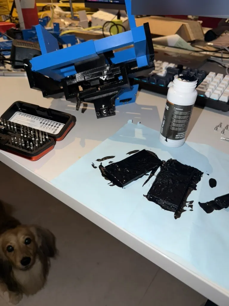
The next evening, 25 days after the arm went on my table, the right arm picked up a real brick for the first time, with G2 in a rev E housing. In the clip the arm lifts the brick off a stack of timber offcuts and sets it down on the lid of the tool case, and the brick stays put when the jaws open.
I checked the design against the job from scratch, and G2's last revision, the twelve-window E.8b from Topology Optimisation, missed seven of the sheet's 21 rows. The requirements started from the brick, not from G2: 2.5 kg, picked from above, carried, and laid level to ±2 mm in mortar. Two rows mattered most.
The grip row needs 60 N on each pad, which through G2's sliding sleeves takes 3.45 to 4.26 Nm at J8. The DM4310 is rated at about 3 Nm and J8 was capped at about 1.7 Nm, so each pad got about 30 N.
The mass row read 1,251 g against a budget of 1,000 g. The housing is 230 g, and the jaws with the printed rails they slide on are 438 g. That row also caps the lever arm, the brick's distance from the wrist, which matters more than mass. Raise the brick 30 mm towards the wrist, with a 1.0 kg gripper, and the sideways torque on J7 drops from 8.73 to 6.55 Nm.
What we built next is the G3, our final right-hand gripper. It's compact on purpose, built for mobility and range of motion. It keeps G2's J8 motor, pinion and racks, and it hangs from the arm's stock aluminium hand plate.
G2's housing sat inside the sweep of the J6 fork, which stopped the wrist roll at about ±40° on the arm. The G3 keeps everything below that sweep, so J7 turns ±90°. It's 140 mm wide against 218 mm, and about 715 g against 1,251 g by CAD estimate.
In a kinematic simulation with no scene collisions, the G3 reaches 52 % of the places on a wall parallel to the shoulders, against 27 % for G2. The figure compares G2's last revision and the G3 row by row.
Mass
Width
Wrist roll (J7), each way
Wall places reachedsimulated, wall parallel to the shoulders
Brick centre off the wrist axis
J6 torque with a level brick
Gap to the body when the arm hangs
- Jaw opening
- Rev E 84 to 136 mmG3 90 to 130 mm
- Tightest strength row
- Rev E the printed root pegs: 34.19 of 35 MPa at the 9 N·m wrist proofG3 the printed pinion teeth: margin 2.9 at a 2 N·m grip with a 3 g stop. The root is the stock aluminium plate, margin 3.1 or more
- Grip
- Rev E rack and pinion on J8, about 1.0 N·m to hold the brick; the jaws open with the power offG3 the same motor, pinion and pads, about 1.0 N·m to hold the brick; the jaws open with the power off
Rev E.8b: its build checks and the measured wrist stop on the arm. G3: its design study and CAD checks. Both masses are CAD estimates. Reach comes from a kinematic simulation of a wall parallel to the shoulders. The strength rows are hand formulas for printed PETG at 35 MPa in the layer plane and 20 MPa across layers; the plate is taken as 5052-H32 aluminium.
The model itself is the last step of the evolution figure in Gripper as Code. The loop below is 52 renders of G2 over a brick, from rev B to E.8b.
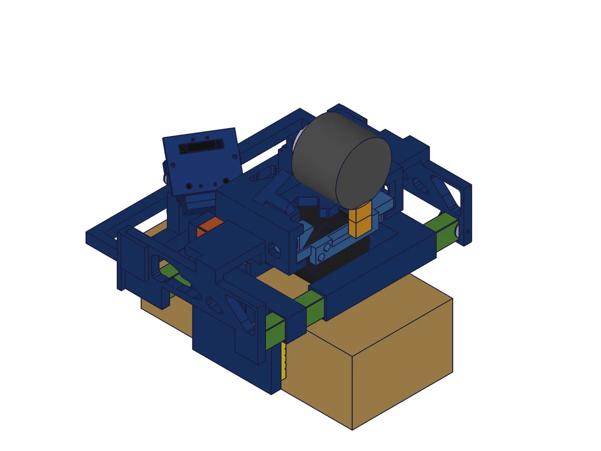
- Rev
- E.8b
- Frame
- 52 / 52
52 renders of the whole assembly from the CAD model over seventeen days, each scaled and moved so the brick sits on the same pixels. OpenArm parts by Enactic appear in some frames (CERN-OHL-S-2.0).
Mortar on Paper
The left arm lays the mortar, and after the first brick it still had no tool. It had J8, a spare 300 g DM4310 motor on the wrist, with about 70° of travel from the trigger in teleop. The tool budget was the gripper's, about 1 kg loaded.
First I worked out what lime mortar will and won't do. The figure sketches the three results.
The bed
heap height 2τ0/ρg, about 10 mm
Below its yield stress the paste holds like a solid. Above it, it flows. So a lump on a board is a 10 mm sheet unless something walls it in.
The perp
free layer holds while τ0 > ρgt
The perp is the vertical joint. A flat pad on the brick end slides off: it needs 196 Pa at 10 mm and 255 Pa at 13 mm. A wedge thins to 8 mm at the top and stands on the fresh bed (the grey strip).
The laid brick
holds 2 to 4 N sideways
A brick on a fresh bed resists only this much sideways push, so the tool must not lean on it.
What a free vertical layer needs, against the lime
- Lime yield
- about 100 Pa
- Heap stands
- about 10 mm
- Free 13 mm pad needs
- 255 Pa
- Laid brick holds
- 2 to 4 N
Arithmetic on one measured yield stress: a KU Leuven vane reading of a lime mortar, 98 Pa at 30 minutes and 116 Pa at 60, not my own mix. A heap stands to 2τ0/ρg and a free vertical layer t thick holds while τ0 > ρgt, with ρ = 2,000 kg/m³ and g = 9.81 m/s². The wedge is 13 to 16 mm at the foot, about 8 mm at the top, laid last and wiped upward at 3 to 6 N. The 2 to 4 N a laid brick resists is an estimate from my mortar research, not a measurement. Sketches not to scale.
Below its yield stress lime mortar holds its shape, and above it the mortar flows. The one measured value I had came from a KU Leuven study: 98 Pa after 30 minutes and 116 Pa after 60, so about 100 Pa at the wetness a mason works at.15 At that, a heap stands only about 10 mm high.
A free vertical layer only stands if its yield stress beats its own weight. That needs 196 Pa at 10 mm thick and 255 Pa at 13 mm, about twice what the lime gives. Fired clay also pulls the water out of the mortar within about 3 minutes, and the brick has to land within about 60 s of its bed.16 And a brick on a fresh bed resists only an estimated 2 to 4 N of sideways push.
So the joint is an L, laid with one hand. The bed goes down first, then the perp, the vertical joint between two bricks, goes up the end of the brick already laid, so the right arm can press the next brick into both.
A plain 13 mm pad would slide off as it's laid, so the perp is a wedge, 13 to 16 mm at the foot and about 8 mm at the top. It's laid last and wiped upward at 3 to 6 N for at most 5 s. Its 8 mm top still needs 157 Pa, and the fresh bed under its foot holds it up.
Drag the slider to thicken a free layer and see the yield stress it needs.
- Pad
- ρgt 255 Pa > τ0 107 Pa: slides at about 0.28 m/s
- Wedge at z = 32 mm
- 12.1 mm, 237 Pa, 2.21x τ0
- 8 mm top needs
- 157 Pa
- Free slices failing
- 7 of 7
Model: a free vertical layer holds when τ0 > ρgt, ρ = 2,000 kg/m³, g = 9.81 m/s². The slide speed is a Bingham layer, v = ρg(t − τ0/ρg)²/2μp with μp = 2 Pa·s (0.14 m/s at 150 Pa and 13 mm); the pad moves at 1/50 of it. The wedge runs 13 or 16 mm at the foot to 8 mm at the top over 65 mm; the bed root supports the bottom 16 to 32 mm (the final concept card for the perpendicular wedge).
Then, in one evening and night, I ran 768 agents that screened 103 concepts against the mortar physics, built 100 of them as CAD models and argued 2,729 challenges. With the other 3 and two smaller rounds from earlier that day, that's 118 distinct designs in CAD, from 119 builds.
Each concept got a card with a low, mid and high value for every number, checked against the rheology above: yield stress, heap height, the free perp and what a laid brick takes. It was also checked on loaded mass against the 1.0 kg budget and on J8's 70° of travel, and scored on pickup, bed and perp.
Each challenge had to be conceded or answered with a number, and 2,554 of the 2,729 (94 %) were conceded. So 69 of the 103 verdicts moved down and none moved up. The screen promoted 0, sent 20 to a bench test, parked 64 and killed 19, each on the one number that decided it. The flow below runs from each card's first verdict on the left to its final verdict on the right.
- bench → park
- 55 concepts
- Moved down
- 69
- Moved up
- 0
- AG16
- AG18
- AG19
- AG20
- AG21
- AG25
- AGP1
- AGP2
- C06
- C09
- C11
- C12
- C16
- C17
- C19
- C20
- CX17
- CX20
- CX21
- CXP3
- F1C
- F1G
- L10
- L11
- L12
- L13
- L14
- L3
- L7
- L8
- N1
- N3
- O2
- O4
- PT1
- PT2
- PT3
- PT4
- PT5
- X1
- X10
- X11
- X12
- X13
- X16
- X5
- X7
- X8
- X9
- XN10
- XN2
- XN5
- XN6
- XN7
- XN9
Computed from the 103 concept cards of my breadth pass: each card's own verdict, and its final verdict after two refuting agents and a further screen attacked it. Bands drawn to scale, one unit per concept.
My own idea was a centrifugal pump, and its number killed it. At J8's 200 rpm an impeller of 30 mm radius gives about 800 Pa at best, and a 90 × 10 mm slot nozzle alone needs about 660 Pa of that. Its card put the pump at about a quarter of the pressure it needs.
Mass was the tightest number. The mortar plus the motor take 0.82 kg for a 260 ml bed and 0.98 kg for a full L of 340 ml, out of the 1.0 kg budget. Only 11 of the 103 came in at or under it. The strip below puts every concept's loaded mass against that line.
- bench
- park
- kill
- L1
- 1.19 kg mid (1.09 to 1.25), bench
- At or under 1.0 kg
- 11 of 103
- Under 1.6 kg
- 93 of 103
- Mortar + motor
- 0.82 kg bed, 0.98 kg full L
At first, 1.0 kg read as the line.
Loaded mass low / mid / high from the 103 final concept cards. Floors from my mass budget: 0.82 kg for a 260 ml bed plus the 300 g motor, 0.98 kg for a 340 ml full L. The toggle shows my later decision to treat 1.0 kg as a target. Linear axis to 2.2 kg, compressed past the break.
The 1.0 kg was my own budget and not the arm's limit, so a tool between 1.0 and about 1.6 kg gets judged on reach and sag. That kept the lead design in at 1.19 kg. It's a bowl on J8 with a vane that wipes the mortar out, a comb for the two ridges a bed needs, and a nose that sets the wedge.
Each of the 100 models is its own geometry script, all written in parallel. The builds ran one after another, because the CAD engine holds one drawing at a time, and all 100 built in under an hour. The replay below shows that run.
- Time
- 55 min
- Specs
- 100 / 100
- Built
- 100 / 100
- Failed
- 0
Viewer updated at 55 min: 100 of 100 built, no build failed.
The run record of the model workflow: 55 minutes, 202 agents, 100 of 100 models built and none failed. Per-agent times are not in the record, so the timing is schematic: specs all done by 8 min, builds evenly spaced from 8 to 53 min, the viewer agent from 53 to 55 min.
The explorer has all 118: the 103 from the screen, plus 13 from a first round and 2 from a second, earlier that day. Each opens as a rough 3D model over the brick course, and the 103 have their card too.

The concept cards and the ledger of my breadth pass, with one CAD proportion model for each of the 118 concepts.
One Bowl
The sweeper came out of that screen: one bowl and one vane on one motor. It went from a decision to a first print on the left wrist in just under 24 hours.
A bench test set the design first. I mixed my first real batch, lime putty and sand at 1:4, until it felt like the mortar from my bricklaying course, and pressed a 50 mm printed disc into it on a kitchen scale. The pushes read 230 and 330 g, plus an outlier of 690 g from a bowl with less mortar in it.
Converted, that's 185 and 265 Pa, which is 1.6 to 2.7 times the 98 to 116 Pa the cards had assumed. A hand-made wedge on a soaked brick also stood for 60 s without moving. Stiffer mortar needs more force at the vane, and a gear for more sweep would halve that force. So the design has no gearing and the vane sits straight on the motor.
This is the sweeper as printed. The vane, in gold, sweeps through its 69° on a loop, and you can turn the model while it plays.
My CAD model of the sweeper as printed for the left arm (build S1.4), exported as glTF, wrist frame in mm. The bowl is a quarter circle of radius 68 mm and the vane sweeps 69 degrees about the gripper motor's axis. The motor and the bricks are not in the model.
The bowl is a fixed quarter-circle of radius 68 mm, centred on the J8 axis. J8 turns a printed vane inside it through 69°, just inside the 70° it gets from the trigger. A comb gate at the foot splits the mortar into the two ridges a bed needs, and two cheeks 104.5 mm apart straddle the 102.5 mm brick, 1 mm a side. I fill it by hand, 252 ml at a time.
I took the rules from the gripper: every tool reports weight, centre of gravity, size, which hand it fits and range of motion first, and it mustn't limit any joint's range. The model puts the sweeper at 583.8 g dry and 1,056.3 g loaded. Its centre of gravity is 86.3 mm below the wrist centre, with 0.97 Nm on J6.
The render adds the J8 motor and the course the tool rides over.
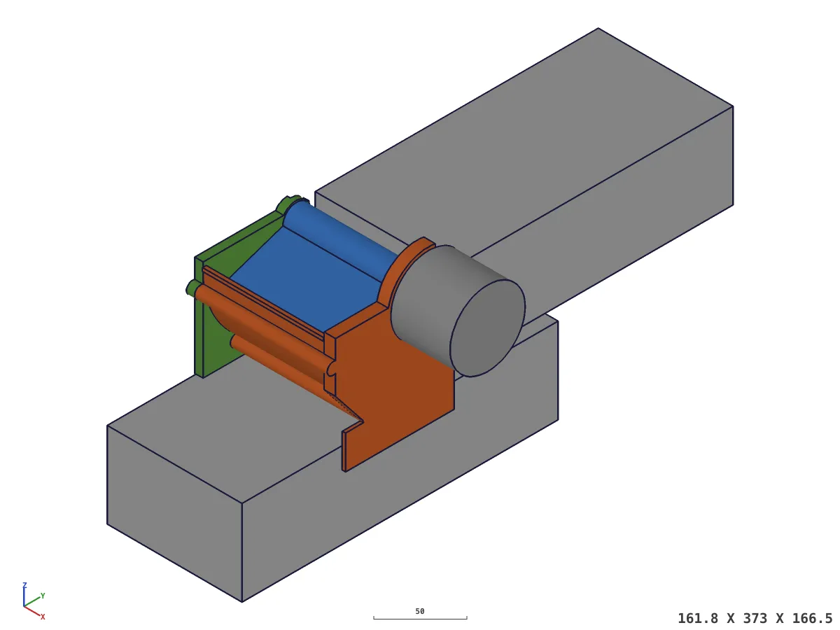
I caught four things before the first real bed:
- The dock. The sweeper can't scoop, so I designed a dock to refill it from, a printed chimney of putty under a weighted follower. It passed its own checks, but the physics ruled it out. Mortar left to stand stiffens to 400 to 800 Pa within an hour. Three gaps in the dock were no wider than the 3 mm sand, so the vents would pass lime and water and hold the sand back like a filter press.
- The grain. A 3 mm grain caught at the vane tip needs about 15 N to pass, and J8 at its 1.0 Nm cap gives 14.8 N. So the sweeper runs with the cap at 2.5 Nm, which gives about 37 N.
- The left hand. It isn't a mirror of the right. The J8 motor is the same part on both arms, with its dowel holes 15° clockwise of the bolts, so a mirrored tool puts them 30° out. A check script now reads the hole angles off the mesh. The first print failed it and went on the wrist without its dowels, and the rebuild from the left arm's own reference model passes.
- The cheeks. The twin, our MuJoCo physics simulation of both arms and the bench, showed the scripted bed sitting 0.7 to 0.95 mm off sideways. With 1 mm a side the cheeks grazed the course in 230 of 256 planned beds, so the next print has 3 mm a side.
The bed motions come from the twin. I planned the wall's five beds there, each a 214 mm drag along the course that takes 48 to 62 s, and the arm replays them. The vane turns in proportion to the distance the tool has moved, so every millimetre gets the same mortar.
I also trained an RL policy on top of that plan. It's PPO, run across 8,192 copies of the twin at once on two GPUs. It has no camera, and reads the joint positions and velocities and how far along the bed it is. It adds a small correction to each planned joint angle, up to 0.05 rad. During training the twin randomises the encoder bias, the motor gains, the joint friction and the masses, so the policy can't rely on one exact robot.
The wall used the planned beds. With no randomisation the planned bed on its own succeeded 100 % of the time in the twin, with a height error of 0.63 mm. The policy's best was 19 % (3 of 16 test beds) after 4,098 iterations in 2.89 hours. The clip is a test rollout from that training run.
First Wall
The two arms laid a wall of five bricks in real mortar, three on two. The left arm spread each bed with the sweeper from One Bowl, and the right arm placed each brick with the G3. A recursive state machine ran the lay, with me approving each place. This section is how it works.
Before either arm moves, the robot has to know where the bench is. A stereo depth camera on its head gives a distance for every pixel, and AprilTags, printed square markers, tell it which flat surface is the bench. Once a brick is down, the same camera measures it.
This is one frame from that camera as 65,691 points. Turn it and look at the bench from the side.
- Points
- 65,691
- Plank top
- 259 mm (built to 261)
- Camera
- 61° below level
- Levelled
- 2.6° on the plank
One ZED Mini snapshot from the head camera (NEURAL_PLUS depth, 1920 × 1080, fx 1507.8 px, 63.1 mm baseline, depth for 91 % of pixels). Every 4th pixel with a confident match, back-projected with the intrinsics, levelled by the IMU's gravity vector and then 2.6° more by a plane fit to the plank top, placed at the measured head pose (x 0.080 m, z 0.779 m), and cropped to the bench and the desk under it. The bench was built to 261 mm, but the tape found the plank at 250 mm a few hours after this frame, so the figure shows the method, not a 2 mm agreement.
The plan starts from the camera too. I draw one datum line on the head camera's video, and the wall planner turns it into brick slots in stretcher bond, 225 mm apart along the wall. A course is 68.5 mm, because the bricks on the bench are 58.5 mm high, not 65. The dashboard I run the robot from then draws each slot over the live video as an augmented-reality (AR) box in its true 3D position.
I try the motions in the twin first. It runs the arm's real safety guard, so a planned motion meets the same checks in simulation as on the arm. I planned the sweeper's five beds there and the G3's carries, with the laid bricks in the scene so a carry can't clip them. We also trained an RL policy in the twin to add a small correction on top of each carry, and on the real arm it carried a brick to the hover above its slot with the joints within 1 mm of the plan.
The dashboard's Cockpit page puts all of it on one screen, so I can see whether the bench the code thinks is there matches the one the camera sees. Look at the 3D view next to the head camera, with both arms at their live joint angles over the depth cloud.
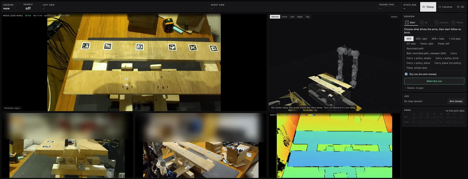
The recursive state machine sequences the two arms. It has fifteen states, and every brick runs through all of them. A brick goes like this: survey the wall and pick the next slot, slide the bench under the sweeper and look, load the sweeper, lay the perp and the bed, retreat, slide the bench under the G3 and look, hand the brick in, carry, place, retreat and verify.
I start every arm job, and the machine asks me for a word before each step (moved, loaded, handed, accept, redo). One arm moves at a time, and a stop in any motion goes to HOLD, where nothing resumes by itself. It has 803 Python tests and 197 dashboard tests passing.
The replay below is the whole lay in the twin, from the planned motions. Press play or jump to a brick and watch the bench slide between its two stops.
SURVEYThe head camera measures the wall: every laid brick, the next slot.
- State
- SURVEY
- Brick
- c1b1 · 0 of 5 laid
- Bench
- —
- Twin time
- 0 of 636 s
The twin's plans for the five bricks of the first wall (beds raised 20 mm, the rev F bench with the slot at y +0.125 m for the bed and −0.200 m for the place), sampled at 25 Hz: 15,908 frames, 636 s of twin time. Kinematic playback of the plans: no guard and no dynamics. Bricks 65 mm tall, the CAD's size; the real ones are 58.5 mm. Arm meshes: OpenArm v2 from openarm_mujoco 2.3.0, copyright 2025 Enactic, Inc., Apache License 2.0, decimated to 16 % of their faces.
The bench slides because no spot in front of the arms works for both. I'd assumed the wall would go where they overlap. A sweep in the twin tried a template wall at 1,584 poses, 22,176 slots in all, with the sweeper on the left wrist and the G3 holding a brick on the right.
On walls parallel to the shoulders the sweeper could bed only from y +0.080 m on the robot's left, and the G3 could place only up to y −0.0075 m. That's a gap of at least 8.8 cm. Of the 1,848 slots on those walls, 39 got a bed, 514 got a place and none got both.
In the map, the dark cells got a bed, the grey cells got a place, the gold band is the gap no slot crosses, and the arrow is the slide that closes it.
- Bed: the left arm lays it with the sweeper
- Place: the right arm sets the brick with the G3
- Tried, neither arm
- Slots
- 22,176
- Both, parallel walls
- 0 of 1,848
- Gap, at least
- 8.8 cm
- Bench slide
- 0.325 m
The joint reach map (a reach sweep in the simulation, 1,584 wall poses, 22,176 slots, 24 minutes on 16 cores): the face line at x 0.18, 0.24 and 0.30 m, its start at y +0.35 to −0.15 m, the plinth top at z 0.22 to 0.34 m, twelve wall directions, the template wall 4, 3, 4, 3 at each, asked of the twin's arm models alone. Drawn: the 1,848 slots of the walls parallel to the shoulders, binned by brick centre (25 mm): 0 of 1,848 got both, and the gap is 8.8 cm only at the narrowest pose (x 0.24 m, z 0.26 m), wider at the rest. Over all directions one slot of 22,176 got both, at x −4 cm, behind the shoulders, not a wall.
This is the same gap in 3D, from the front of the robot.
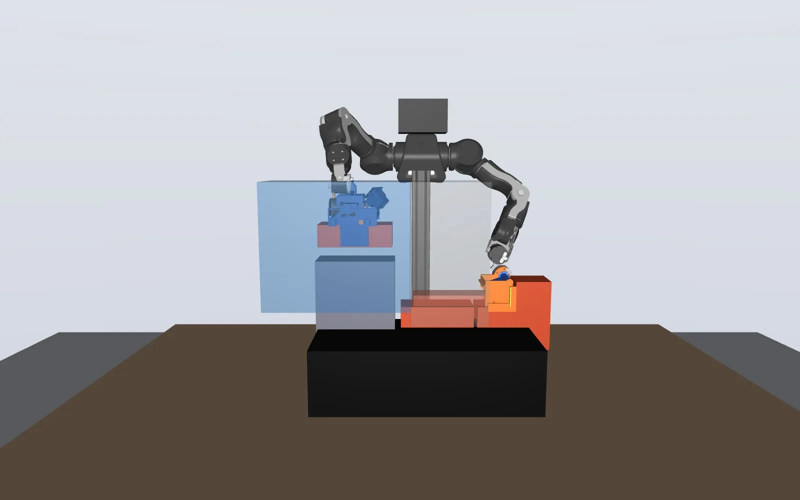
So I built a bench that takes the wall to each arm in turn. It has a bed stop at y +0.125 m under the sweeper and a place stop at y −0.20 m under the G3, 0.325 m apart, and I slide it between them by hand. The machine checks every slide against the twin and tells me how far to move the bench if it's off, and the head camera finds the wall again before any arm moves.
The bench is one 700 × 100 × 17 mm ply plank on two posts, its top 261 mm above the desk. A third course would need half bricks, so the first wall is three on two. Turn the model to see the plank in gold with the wall on it.
My CAD model of the rev F bench (41 bodies, 3,324 triangles), robot frame in mm. The 3-on-2 wall on it uses the 65 mm brick of the CAD, and the real brick is 58.5 mm. The tag rail went on behind the plank later and is not in this model.
Four fixes came before the lay. On a dry run the AR brick sat below the real plank, so I got the tape measure out. The left eye of the head camera was 779 mm up where the CAD had 833.25. So the robot had been looking at the bench from 54 mm too high, and I put the measured pose into its config.
The code took the biggest flat plane in view as the bench, and that was the desk, so it found 0 tags while the camera could see eleven. Picking the plane that holds the most tags took it from 0 tags to 10 of 10.
Three bricks cover 665 of the plank's 700 mm, so once the first course was down there'd be no tag left to find the bench by. I added a rail behind the plank, flush with its top, with six 30 mm tags set far enough back that the camera sees them over a two-course wall. The drawing shows the rail and the 15 mm gap I left for the sweeper's far cheek.
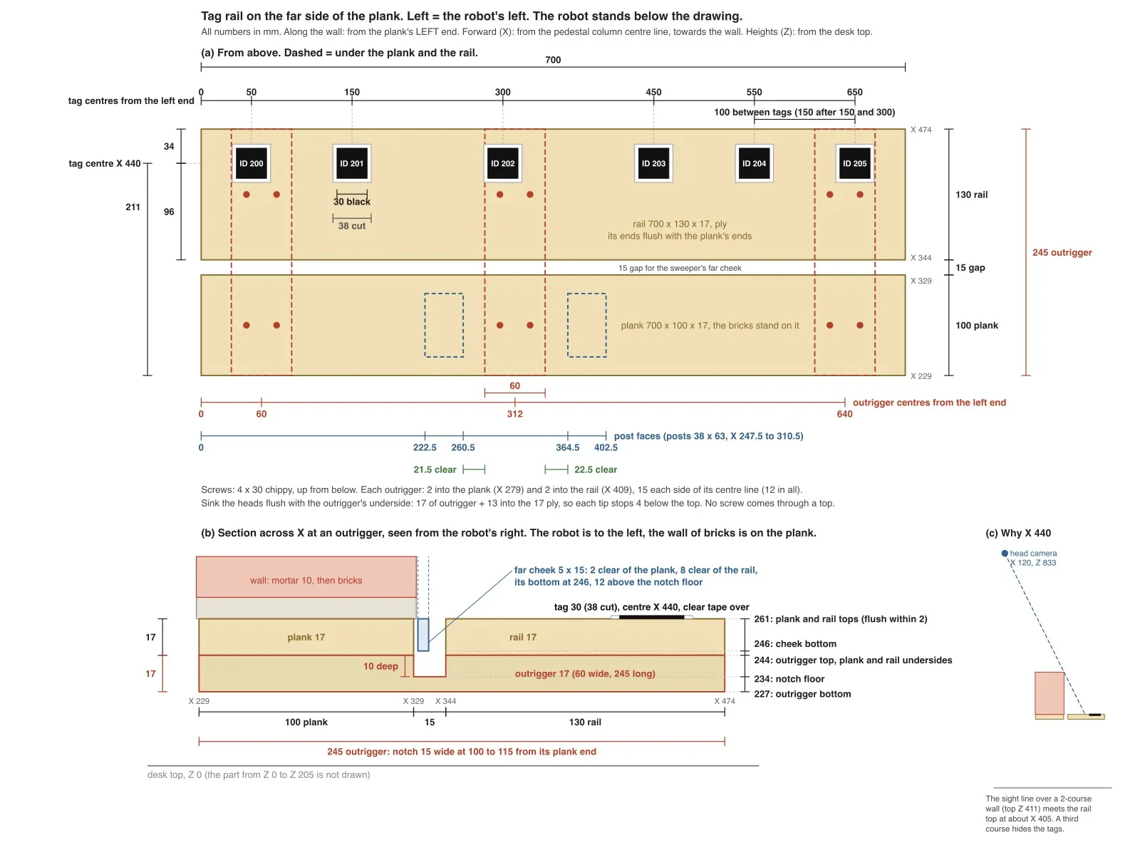
On the first empty bed on the real bench, the safety guard stopped the left arm 30 s in, with the wrist at 3.7 Nm and the sweeper's cheeks pressing into the plank. The guard was right, so I raised the bed motions by 20 mm.
For the lay I skipped soaking the bricks, because a wet brick is heavier for the arm. The bottom course went down first, three bricks, each on its own bed, and then the two on top. The checks worked on every brick. One place was stopped because the camera put the brick more than 20 mm from its slot, so I jogged it and released.
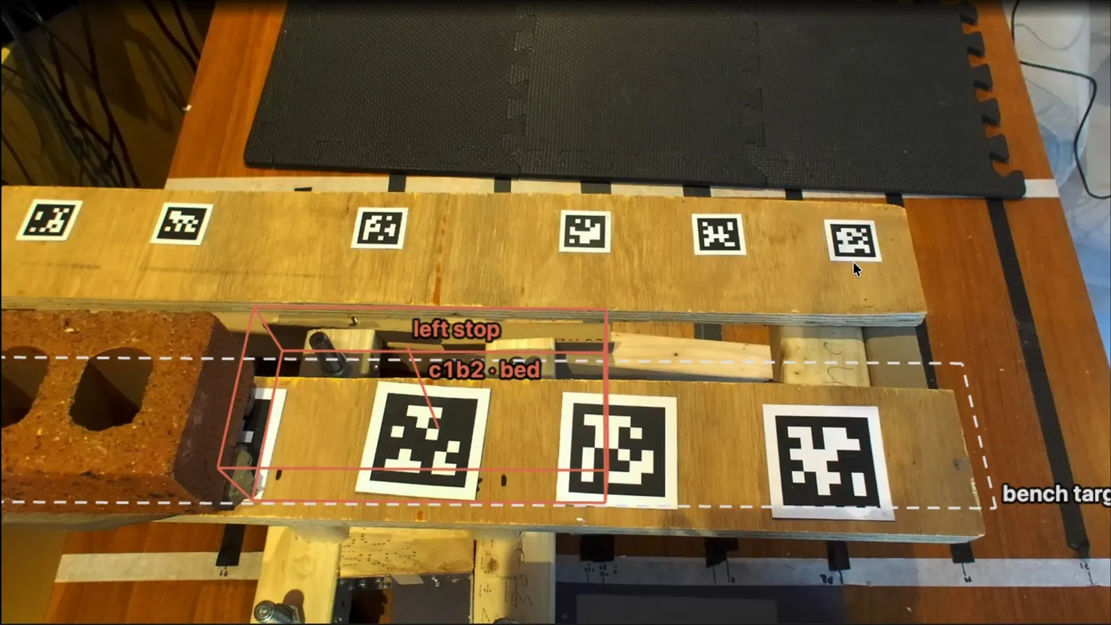
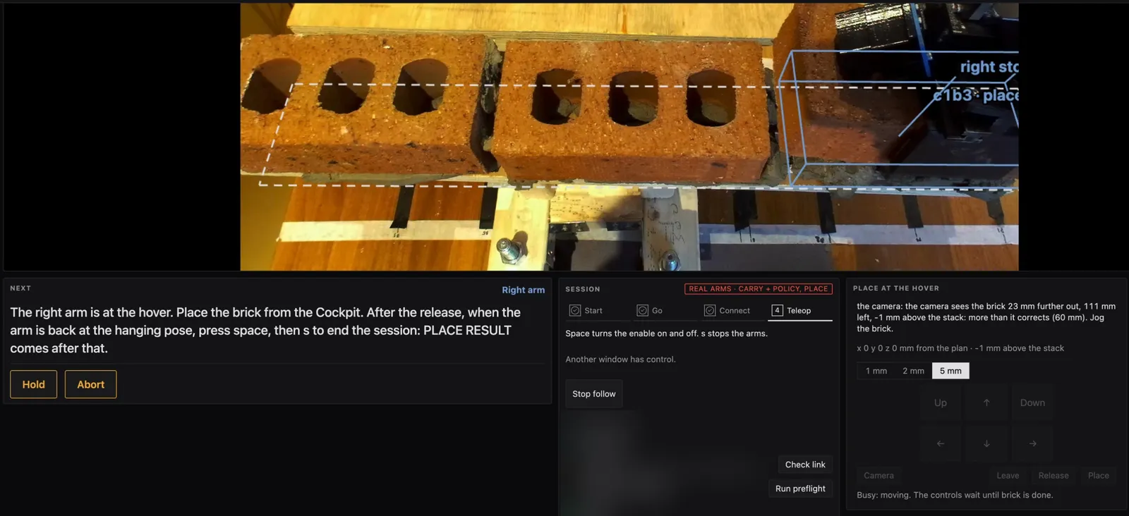
These two stills are the AR during the lay, at the second bed and at the third brick.
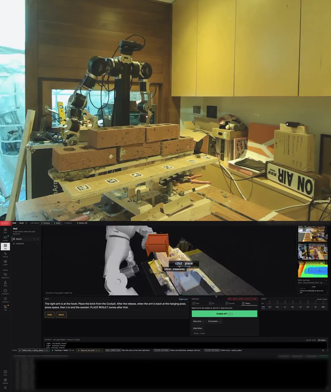
All five went down, and the dashboard counted 5 of 5. This is the wall, in a still from the clip at the top of the post.
What Comes Next
We have a wall. Now we need to make an actual good wall. That means the robot checks its own work on the four checks from Learning the Trade: gauge, level, plumb and line. The first wall was laid to a plan and not yet judged on them.
These are the things to improve for the second wall, in order. The grip held, so it isn't on the list.
- Close the feedback loop. The state machine puts each brick where the plan says its slot is. The next version corrects its own placing error: locate the brick, verify it, work out the offset, correct, place. We have two numbers to beat. The first brick sat about 50 mm from its mark by the dashboard's reading, and bed to place took 6 to 36 minutes where the plan wants 60 seconds.
- Measurements we trust. The loop needs them. The dashboard already measures the gaps between bricks and their tilt, but so far only on good bricks, not on a real course, and it read the 700 mm plank as 690. Our guess is the camera code, which assumes the bench is level when ours was slanted. The bench measurement also reads 12 mm forward and 12 mm low of the tape. More cameras on the scene from different sides would let us check one against another.
- Calibrate the wrist limits. On the third brick a place was refused with J7 at 89.4° against a limit of 90°, inside the guard's 1.15° margin. We want the joint limits calibrated, and to know whether each one came from the stock values or from our own.
- Speed. Laying faster needs stronger motors, because these ones lose torque as the speed goes up.
- The left hand. The sweeper runs a scripted bed and it's very sensitive to height. Its cheeks sit either side of the brick and should tell it when it's done, so it needs feedback too. For loading, the idea is cartridges pre-filled with a set amount of wet mortar that the arm swaps itself, with triangular extrusions on the hand to help spread it.
- Mobility. Today I slide the bench by hand. Next the robot itself has to move left and right.
Footnotes
-
Brian Potter, "Where are the robotic bricklayers?", Construction Physics, 29 July 2021, construction-physics.com. ↩
-
FBR's ASX announcements. The rates are FBR's own figures, not independent measurements. The US agreement with CRH set a contractual threshold of "at least 285 blocks/h": ASX announcement, 18 January 2024, CRH agreement. ↩
-
The top comment in an r/masonry thread, 4 June 2025, Reddit. ↩
-
Charlie Collison, "ROBOT Bricklayer VS REAL Bricklayer (3000 Brick Challenge)", YouTube, 10 August 2021, YouTube. The 840 per person is my arithmetic. ↩
-
OpenArm docs, OpenArm KER general and KER setup: a motorless shoulder-mounted leader, 1.7 kg, 16 TLE5012B encoders, 70 % link lengths, one USB-C cable to the PC. ↩
-
enactic/openarm_can issue #102, "Can we support MacOS?", open at the time of writing, GitHub. ↩
-
Enactic, dora-openarm-data-collection, the version of 24 September 2026, with dora-cli 1.0.1, GitHub. ↩
-
Enactic, OpenArm issue #87 (April 2025), a payload test on an earlier OpenArm, GitHub: "up to ~3kg not including the end effector" in the normal workspace, and "1.6kg ... Arm triggered safety mechanism at max reach point". The 4.1 kg rating is the seller's, from the leaflet in the box, and it includes the end effector. ↩
-
Enactic's official OpenArm v2 STEP file, GitHub, and Damiao's DM4310 drawing. The joint 7 child link is discussed in enactic/openarm_description issue #77. ↩
-
The yield stress range of 80 to 400 Pa is from Banfill (2006), as quoted in Hendrickx, Minet, Van Balen and Van Gemert, "Workability of mortars with building lime: assessment by a panel of masons versus lab testing" (KU Leuven, about 2008), lirias.kuleuven.be. The 2 to 23 N bed force is arithmetic from that range, not a measurement. ↩
-
The ring geometry comes from Enactic's OpenArm 2.0 STEP file, GitHub, released under CERN-OHL-S-2.0. ↩
-
K. Liu and A. Tovar, "An efficient 3D topology optimization code written in Matlab", Structural and Multidisciplinary Optimization 50, 1175-1196 (2014). ↩
-
M. P. Bendsøe, "Optimal shape design as a material distribution problem", Structural Optimization 1, 193-202 (1989). ↩
-
A. G. M. Michell, "The limits of economy of material in frame-structures", Philosophical Magazine (6) 8, 589-597 (1904). ↩
-
Hendrickx, Minet, Van Balen and Van Gemert, "Workability of mortars with building lime: assessment by a panel of masons versus lab testing" (KU Leuven, about 2008), lirias.kuleuven.be, Table 5, binder 1 (CL90 lime and sand, no cement): 98 and 116 Pa after 30 and 60 minutes at rest. The literature range is 80 to 400 Pa. ↩
-
Brocken, Spiekman, Kopinga and Larbi, Materials and Structures (1998): fired clay extracts the water "within 3 minutes", and "Prewetting a fired-clay brick hardly affects the water extraction". BIA Technical Note 7B: "Brick should be laid within about 1 minute after the mortar is placed". The 2 to 4 N hold of a brick on a fresh bed is an estimate, not a measurement. ↩